

What Is CNC V Grooving Machine
With the rapid development of my country's industrial system, more and more companies have higher and higher requirements on the bending process of metal sheets, including some other sheets, so more companies choose to use the sheet metal bending process. It is required to perform pre-grooving processing on the bending position due to market competition factors. Customers' pursuit of product aesthetics is correspondingly increasing, so the grooving process has now become a necessary process before the bending process. With the continuous deepening of the planing process. More industries are beginning to use the gouging process; many of them include some high-tech industries that are also using the gouging process. The main application industries of the planing process include: light industry, electrical appliances, automobiles, stainless steel processing, architectural decoration, furniture industry, kitchen equipment, ventilation equipment, aerospace, elevators, chassis, cabinets, etc. The grooving process includes V-shaped groove processing, U-shaped groove processing and irregular groove processing. Sheet edge chamfering, sheet cutting and planing, etc.

1. The Purpose and Use of Designing and Producing Grooving Machines
1.1 After the grooving machine performs V-shaped grooving on the sheet, the bending angle of the sheet will be easy to form during the bending process, and the R angle after forming will be very small. The workpiece is not easily twisted or deformed, and the straightness, angle, dimensional accuracy, and appearance of the workpiece after bending and forming can all achieve good results.
1.2 After the sheet metal is V-grooved by the grooving machine, the required bending force will be reduced, so that long and thick sheets can be bent on a smaller tonnage bending machine. This will reduce the energy consumption of the machine.
1.3 The grooving machine can also perform pre-positioned marking processing on the sheet so that the workpiece can ensure high accuracy in the size of the bending edge during the bending process.
1.4 Under the special grooving process requirements, the grooving machine can process U-shaped grooves on the surface of some sheets, so that the processed surface can be beautiful, non-slip, and practical for splicing.
2. Classification and Processing Modes of Grooving Machines
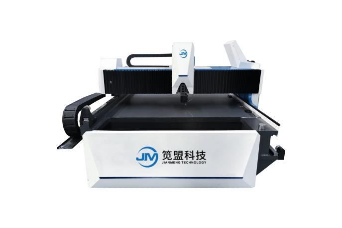
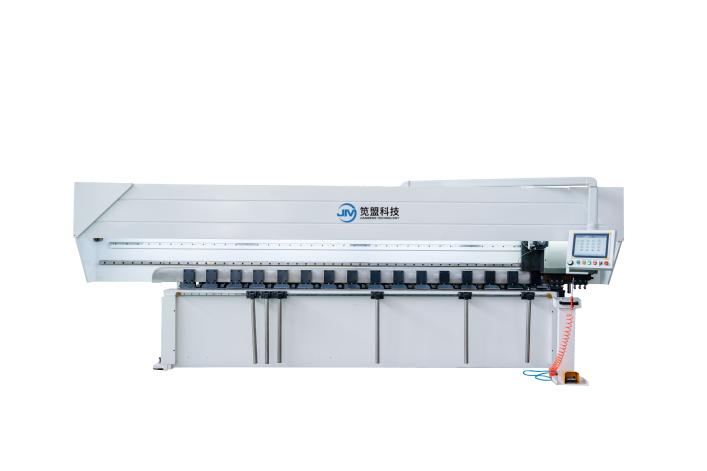
2.1.Grooving machines are divided into two categories: discrete grooving machines and gantry grooving machines (horizontal).
2.2. Vertical grooving machines include single tool holder and double tool holder grooving machines. The single-tool post-grooving machine adopts right-cut grooving. The double-tool holder grooving machine can be divided into right-cut grooving and left-cut grooving. It can also be used with two tool holders to perform right-cut grooving and left-cut processing at the same time. It can also use bidirectional back-and-forth grooving.
2.3.Gantry grooving machines can be divided into single-drive grooving machines and double-drive grooving machines. Both grooving machines use right-cut machining mode.

Horizontal high-speed v grooving machine
Horizontal double drive v grooving machine
Vertical high-speed v grooving machine

Vertical back-and-forth v grooving machine

Fully automatic four-sided v grooving machine
3. Compression and Clamping Categories of Grooving Machines
3.1.Vertical grooving machines can be divided into hydraulic devices, pneumatic devices, and gas-liquid mixing devices.
3.2.The gantry grooving machine, like the vertical grooving machine, is also divided into hydraulic device, pneumatic device, and gas-liquid mixing device.
4.The Structure of the Grooving Machine
4.1.Vertical grooving machines can be divided into two types: full-body welding and screw-type connections. Because screw-type connections will cause looseness and deformation of equipment connections during the lifting and transportation of the equipment, the full-body welding type is generally used. The main welded large parts of the machine bed are tempered with natural gas to eliminate stress. After welding, the whole machine is processed using a gantry CNC machining center.
4.2.The gantry grooving machine adopts full-body welding technology. The entire bed and gantry are tempered by natural gas to eliminate stress, and then the entire machine is processed using a gantry CNC machining center.
4.3.The body structure of the vertical grooving machine consists of left and right columns, a workbench, a tool rest pressure plate, a cross beam, a rear gage frame, a planning tool rest, and other main components.
4.4.The body structure of the gantry grooving machine consists of main components such as the workbench, gantry frame, and tool rest.
4.5.Vertical and gantry grooving machines not only eliminate stress but also ensure excellent paint effects through sandblasting.
4.6.The workbench panels of vertical and gantry grooving machines are all welded with No. 45 steel. The frame is welded with a Q345 steel plate. The overall machine tool has good rigidity and is strong and durable.
5. Working and Driving Principles of Grooving Machine
5.1.Working drive of the vertical grooving machine
a.The workbench of the grooving machine is designed to have a humanized height of about 850mm. The work surface is designed with a high-strength 9crsi material table below the running path of the tool holder, with a chromium hardness of 47-50 degrees to ensure the durability of the work surface.
b.The drive of the grooving machine is composed of X, Y, Z and W. The X-axis, Z-axis, and W-axis are respectively installed on the pressure plate beam. The X-axis is the processing and cutting axis, which mainly controls the length of sheet metal processing. It is driven by a 3-module helical rack, alloy helical gear, 5.5 kW spindle motor and a 1:5 ratio star reducer. The Z-axis and W-axis are respectively driven by double-nut ground ball screws with a diameter of 32mm. And a 1kW servo motor, two sets of dovetail guide rails and couplings for driving. The Y-axis is the backgauge feed axis. It mainly controls the distance between the sheet processing grooves. It is installed on the backgauge frame of the workbench. It consists of a 32mm diameter single-nut ball screw, a 30mm linear guide rail, and an 8mm synchronous belt. , 1:2 ratio synchronous wheel, driven by 2kW servo motor.
5.2.Gantry grooving machine work drive
a. The bed working platform of the grooving machine is designed to a user-friendly height of about 700mm that can be lifted smoothly by 2 people and loaded without obstacles. The left and right main and auxiliary linear guide rails are designed to be installed on both sides of the workbench. The single-driven gantry grooving machine The rack is installed on the operation control side. The rack of the double-driven gantry grooving machine is installed on both sides of the workbench bed.
b.The drive of the grooving machine is divided into X (beam axis), Y (tool holder left and right movement axis), Y2 (front presser foot left and right movement axis), and Z axis (tool holder up and down movement axis). The X-axis is mainly based on the length of sheet metal processing and is the main cutting axis. It is installed on the gantry and passes through a 5.5 kilowatt spindle motor, a 1:5 ratio star reducer, an 8mm synchronous belt, and two A 1:1 ratio synchronous wheel, an alloy 3-die helical gear and a helical rack mounted on the bed for driving. The Y1 and Y2 axes are respectively the moving feed axes, which mainly control the size of the distance between slots. When the Y1 axis is used for tool holder processing, the positioning axis of the required processing size is also installed on the gantry, through a 1 kilowatt servo motor, an 8mm synchronous belt, two synchronous wheels with a ratio of 1:1.5, and two 30mm Linear guide rail (the upper guide rail is equipped with 2 slide seats and the lower guide rail is equipped with 3 slide seats), driven by a single nut ball screw with a diameter of 32mm. The Y2 axis is the left and right movement platen axis of the front presser foot. It is synchronized with Y1. They all receive instructions for inputting processing dimensions at the same time and run to the required position. The Y2 axis is installed inside the lower part of the bed and passes through a 1 kilowatt servo motor. An 8mm timing belt, two synchronous wheels with a ratio of 1:1.5, a single nut ball screw with a diameter of 32mm, and two chrome-plated polished rods with a diameter of 45mm are used for driving. The Z-axis is the feed axis of the tool holder, which is mainly based on the depth of the sheet material to be processed. It passes through a 1 kilowatt servo motor, a 32mm diameter double-nut grinding ball screw, and two 35mm linear guide rails (each equipped with two slide) and a coupling for drive.
c.If the grooving machine is designed with dual drives and an X2 axis is added, the X2 axis will be designed to run synchronously with the X1 axis.